|
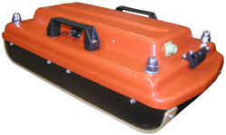
OKO-2 GPR with control unit
The OKO-2 GPR is a portable lightweight low-prices system designed for non-destructive environmental monitoring. The OKO-2 GPR includes control unit or control processing unit and antennas. All antennas are interchangeable and meet the needs of a broad range of applications.
ADVANTAGES
- High accuracy GPR data
- Compatible with all antennas
- Removable rechargable batteries
- Rugged and weather resistant
- GPS integration
- Synchronization of GPR sounding and video recording
- Horn antennas which can be mounted on a vehicle and a railway car (the speed up to 80 km/h)
- Advanced multi-channel multi-frequency system
- Technical support and assistance
- After sales service
- Free training
- 2-year warranty
- CE certificate
|
 |
APPLICATIONS
- Highways, runways, railways embankment examination
- Concrete inspection
- Geological structures mapping
- Utilities mapping
- Ice cover thickness defining
- Buried small object detection
- Basin exploration and near-bottom sediments mapping
- Temporary freezing thickness detecting
- Archaeology
- Many other applications

OKO-2 GPR with a control unit combines:
- Control unit
- Power supply unit BP 9/12
- Power supply unit BP 2/12
- Optical transformer
- Charger ZU-2
- Charger ZU-9
- Changer for a notebook
- Handle-rod (transportation handle or telescopic handle rod - it depends on antenna unit)
- Carry case (bag)
- Software (GeoScan32)
It was designed to operate with a notebook or a processing unit
|
Antenna (AB)
|
Central Frequency (MHz)
|
Maximum depth of penetration (m)
|
Resolution (m)
|
|
ABDL Triton
|
50, 100
|
20
|
0.5-1.5
|
|
AB-90
|
90
|
16
|
0.5
|
|
AB-150
|
150
|
12
|
0.35
|
|
AB-250M
|
250
|
8
|
0.25
|
|
AB-400M
|
400
|
5
|
0.15
|
|
AB-400R
|
400
|
3
(Work with retraction up to 30-40 cm)
|
0.1
|
|
AB-700
|
700
|
3
|
0.1
|
|
AB-1000R
|
1000
|
1.5
(Work with retraction up to 30-40 cm)
|
0.05
|
|
AB-1200 (AB-1200U)
|
1200
|
1.5
|
0.05
|
|
AB-1700 (AB-1700U)
|
1700
|
1
|
0.03
|
|
AB-1700R
|
1700
|
1
(Work with retraction up to 30-40 cm)
|
0.03
|
|
AB-2000R
|
2000
|
0.8
(Work with retraction up to 30-40 cm)
|
0.02
|
GeoScan32
Geoscan 32 is designed for control of the ground penetration radar (GPR), as well as for further processing and visualization of the data obtained in the process of scanning.
Features
- GPR data acquisition with OKO-2 GPR in continuous mode, arrow mode (using odometer) and step-by-step mode
- Data visualization during the survey
- Interactive determination of layer speeds and local objects occurrence depths
- Layer-by-layer processing;
- Area survey data processing
- Terrain correction
- Trace editing
RadExplorer

RadExplorer - is designed for interactive processing and interpretation of GPR data developed by DECO Geophysical.RadExplorer is a specially designed program for GPR (ground-penetrating radar) data processing and interpretation. The options set optimized for GPR data and friendly human-engineered interface allow quick and effective processing of GPR data.
Features:
- Automatic selection of optimum data processing parameters by default depending on the parameters of the data
- Interactive construction of data processing flows with ability to save them on hard disk and re-use with other files
- Unlimited undo of the processing routines
- Interactive detemination of dielectric constant/velocity in the media and depth of target objects
- Reflection picking with saving the obtained picks into tabular text file
Flexible model editor and time-to-depth conversion
RadExProPlus
RadExPro Plus is designed for comprehensive processing and interpretation of near-surface on-shore and off-shore seismic, VSP and GPR data under Windows 9x/Me/2000/XP/Vista.
Scope:
- Reflection data processing and interpretation
- Field quality control (QC) of 2D/3D seismic data
- Refraction seismic data processing and interpretation
- VSP data processing
- GPR data processing and interpretation
RadExPro Plus™ is operating on inexpensive Windows-driven PC's and workstations. Install it onto a notebook and take afield or aboard a research vessel and enjoy all the potential of the full-blown system for seismic processing, interpretation and quality control!
Advantages:
- Convenient and easy data input/output allows loading of seismic and GPR data recorded almost in any format either from disk or tape
- User-friendly graphical interface enables construction of sophysticated processing flows for batch processing of seismic and GPR data
- Exhaustive set of efficient processing and QC procedures
- Set of fast interactive tools for seismic and GPR data visualization and analysis
- Handy interpreation facilities: horizon picking, seismic sequence attribute analysis, interactive map, well-log data visualization
- Flexible trace header management, including mathematical operations with header fields and much more
- Special means for visualization and analysis of header field values
- Powerful and effective data base which allows storing of seismic data, processing flows, well data, picks, velocity data, grids, etc
Open scalable architecture – if you miss a specific module, you can build it yourself and integrate into the package! (Programmers working in MS Visual C++ will be provided with special User Application Wizard).
|
A notebook (Display is 12-14 inches. The size is not more 340x280x35 mm. The weight is 2-2.5 kg. The power consumption 50-60W power supply - 19V, CPU - not less 1 GHz RAM - not less 512 MB, HDD - not less 40 GB, Software - Windows XP/Vista) is used for GPR data processing and interpretation in a field and in the office
|
 |
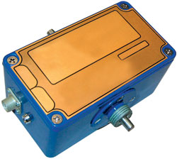
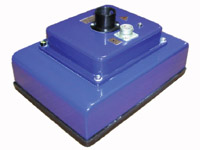
The Control unit
The control unit is designed for control of all GPR operating modes. The control unit receives commands from the notebook computer by Ethernet interface, calculates the current parameters for the antenna and transfers them via RS-485 interface to the antenna, transfers commands of operating mode to the antenna, receives the data from the antenna, makes the secondary processing of these data and transfers the processed data to the notebook via Ethernet interface. The voltage converter, designed for notebook power supply unit is built into the control unit. An external control keyboard and an automobile odometer are provided as extra options.
|
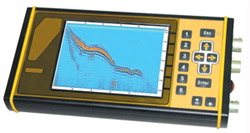 |
The Control Processing Unit
The Control Processing unit is designed to control all GPR operation modes, to display georadiolocation cross-section in the screen, to record them on a flash-disk, to execute the initial processing of the obtained data and to exchange dara with the PC via Ethernet interface. Control Processing Unit operates with the antenna directly, a notebook computer and a control unit are not required in this case. The Control Processing Unit was designed especially to operate in unfavorable conditions and is produced as all weather conditions (temperature -20... +50 °C). Data is put out onto a colored LCD display indicator with an enhanced contrast ratio, size 6.5", with a resolution 640x480 points. The obtained data are recorded on the built-in flash disk with capacity 1 GB. Power consumption is no more than 8W.
|
 |
Radio modem RM-2
The Radio modem is designated for GPR remote control. While working with it the operator with a notebook may be in a place protected from external weather conditions, and at the same time another operator moves the antenna by profile. The radio modem can be used only with the control unit. This set consists of a radio modem (RM-2), a carry bag and the radio modem cable. The maximum remoteness in the open area is 100 m. Connection is accomplished through Wi-Fi.
|
 |
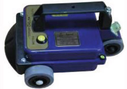
Odometer DP-32
Odometer DP-32 is for exact setup of GPR results to the local area. It is used to move the antenna on a solid surface. Configuration DP-32 allows using it in unfavorable weather conditions. Power is supplied with two elements AA, capacity 1,5V. The data is transferred via the optical cable.
|
 |
Automobile Odometer DPA
Automobile odometer is used during operations upon an automobile, it is connected directly to the vehicle odometer.
|
 |
Odometer Spool
Spool is used during off-road operation or in small water pools. The end of the thread is fastened to the idle object in the beginning of the cross-section. When the antenna is moving, the distance measurement is performed at the expense of the rolling thread. Power is supplied by two AA elements, voltage 1,5 V. Data transfer is performed via the optical cable.
|
 |
AB-1700 Antenna
Antenna with central frequency of 1700 MHz, built-in displacement transducer, depth of sounding up to 1 meter, resolution 0,03 meter
|
 |
AB-1700U Antenna
Multi-purpose antenna with central frequency of 1700 MHz, removable mono ski, opportunity to use both built-in displacement transducer and displacement transducer DP-32, depth of sounding up to 1 meter, resolution 0,03 meter
|
 |
AB-1200 Antenna
Antenna with central frequency of 1200 MHz, built-in displacement transducer, depth of sounding up to 1,5 meter, resolution 0,05 meter.
|
 |
AB-1200U Antenna
Multi-purpose antenna with central frequency of 1200 MHz, removable mono ski, opportunity to use both built-in displacement transducer and displacement transducer DP-32, depth of sounding up to 1,5 meter, resolution 0,05 meter.
|
 |
AB-700M Antenna
|
 |
AB-400M Antenna
Antenna (monoblock) with central frequency of 400 MHz, depth of sounding up to 5 meter, resolution 0,15 meter.
|
 |
AB-250M Antenna
Antenna (monoblock) with central frequency of 250 MHz, depth of sounding up to 8 meter, resolution 0,25 meter.
|
 |
AB-2000R Antenna
Antenna of horn type with central frequency of 2000 MHz, depth of sounding up to 0.8 meter, resolution 0,02 meter.
|
 |
AB-1700R Antenna
Antenna of horn type with central frequency of 1700 MHz, narrowed directional diagram, opportunity to survey at a distance up to 0,02 meter above surface, opportunity of near-surface layer detailed survey, depth of sounding up to 0,8 meter, resolution 0,03 meter.
|
 |
AB-1000R Antenna
Antenna of horn type with central frequency of 1000 MHz, depth of sounding up to 1,5 meter, resolution 0,04 meter.
|
 |
AB-400R Antenna
Antenna of horn type with central frequency of 400 MHz, depth of sounding up to 3 meter, resolution 0,10 meter.
|
 |
Antenna ABDL "Triton"
Antenna ABDL- «Triton» is unshielded antenna with an optical coupling. The receiving and transmitting units are supplied with power from separate power supply units, but to transfer the signal of the transmitter start pulse from the receiving unit to the transmitting one, the optical cable is used. Antenna integrates transmitter, receiver and power supply units in one semi flexible hose.
|
 |
AB-90 Antenna
Antenna with central frequency of 90 MHz, depth of sounding up to 16-18 meter, resolution 0,5 meter with removable wheel system
|
 |
AB-150 Antenna
Antenna with central frequency of 150 MHz, depth of sounding up to 12 meter, resolution 0,35 meter with removable wheel system
|
 |
AB-400 Antenna
Antenna with central frequency of 400 MHz, depth of sounding up to 5 meter, resolution 0,15 meter
|
 |
AB-700 Antenna
Antenna with central frequency of 700 MHz, depth of sounding up to 3 meter, resolution 0,01 meter
|
|